Categories
3D printing Retro gaming

ODROID XU4 cooling

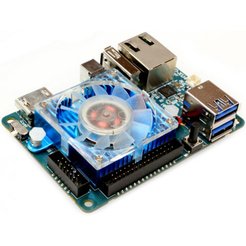
Building an arcade table using an ODROID XU4 SBC (Single Board Computer) to run the emulation under Linux, I found the stock 40mm fan that came with the XU4 was just too annoyingly noisy.

The XU4 with the annoyingly noisy fan.

I needed a solution which was not too tall because I was building this into an Ikea LACK side table so the available space was 54mm high. All the passive heatsink solutions I could find were too tall – the stock passive heatsink in the XU4Q was not enough to stop overheating on its own. I could still hear the buzzy 40mm case fan when enclosed in the table, I decided that I needed a simple, quieter solution which involved moving air and the existing heatsink.

As I also needed a case for the XU4, so I designed and 3D printed a case which would take a top mounted 80mm case fan. I’m using the eMMC to boot so there is a support for that. There are enough side holes for airflow, and to access the various XU4 ports. The XU4 is a snug fit, so much so that there is even a slot cut for the eMMC / SD Card selector switch which protrudes from the edge of the board. I have not found that I needed to screw the XU4 into the case, but that should be fine into one (or more I guess) of the corner quadrant pads.

Get the STL file from here: https://www.tinkercad.com/things/jQjhsvrBTEi

The case isn’t pretty, but it is functional and was designed to be hidden inside an Ikea table so it really didn’t need to be a diamond.
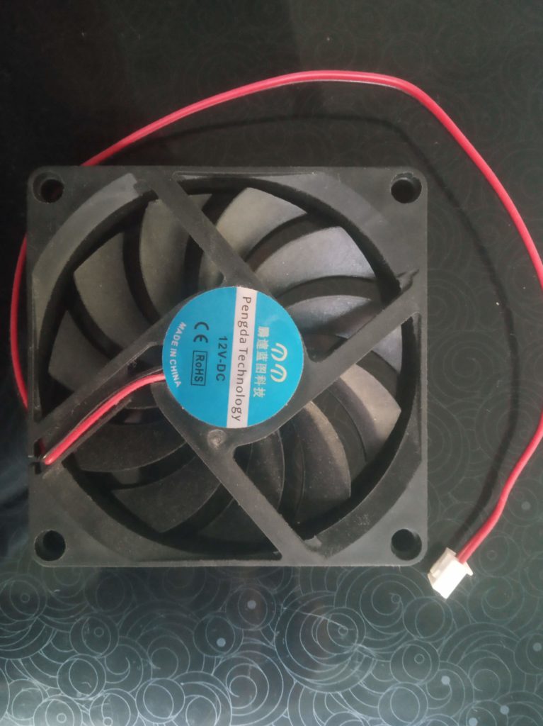
12V DC 10mm case fan

I sourced this 12V DC 2 pin case fan. Assuming the ebay link still exists, this one https://www.ebay.co.uk/itm/383664051536 which is 10mm high. I run this from the XU4, so at a maximum of 5V it runs slower than if run at 12V so quieter. Given that it moves more air than the stock 40mm fan, this seems to keep the board just as cool as the stock fan did, but significantly quieter.

This particular fan seems to be generic, there are lots on ebay / amazon which are similar. I was a bit worried it was going to be too noisy but it turned out to be pretty quiet, perhaps helped because it is being driven at 5V so spinning slower. Just a warning, some 12V fans may not work at 5V. Depending on your available space, you may be able to use a 15mm, 20mm or 25mm width fan. Having a larger area for the bearings, you may find that these fans can be made quieter, so you may be able to use a 5V 80mm case fan. If your fan has more than 2 wires, you should find that you only need to connect the positive and negative, the others can be left un-connected.
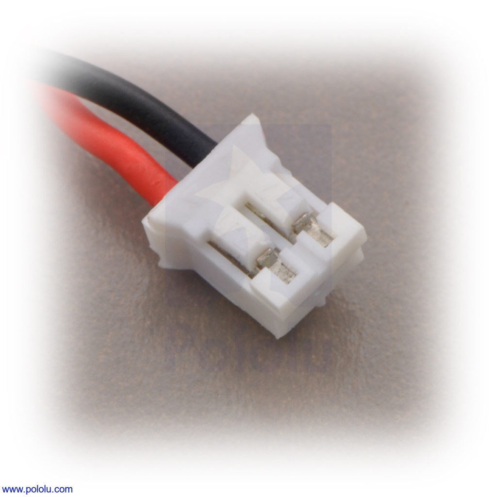
Female JST 1.25 pitch 2 pin connector

Like all case fans I’ve ever come across, this one comes with the wrong sized connector for an XU4 mother board, so I replaced the connector with this female 1.25mm pitch 2 pin JST connector. Again, assuming the link is still there, these ones: https://www.ebay.co.uk/itm/284270706948. This will require some soldering. Once connected, I screwed the fan to the lugs on the top of the case to keep it all secure.

I ran some prime95 tests and could not get the XU4 processor above 85 degrees C. In normal use, running the Naomi / Dreamcast emulator (lr-reicast) from Emulationstation / Retroarch, was probably about the most intensive and the core temperature hung around the 70-74 degrees C mark. This is also sharing a pretty small space with an Iiyama ProLite P1904S which has been dismantled but is still quite a warm beast.

If I did this again I think that I’d use the XU4Q model with the large passive heatsink, using this case / fan to contain and cool that, I think that it would fit ok but may need a shim or slight re-design to make the case walls higher.

I don’t have one but from what I’ve read, this should work on an XU3 without modification. For a Raspberry Pi you would need to do a little modification to the case design. On the Pi you would use dupont style female connectors with a 2.54mm pitch instead of the 1.25mm pitch 2 pin JST connector and connect the red wire to the +5V (GPIO 4) pin and the black one to Ground (GPIO 6) pin.
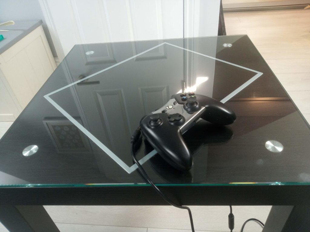
Ikea LACK arcade table

Here is the finished arcade table in case you are interested, we are very pleased with it all in all. I’ll write up how that was made when I get a chance.
Categories
DIY Raspberry Pi Retro gaming

DIY Raspberry PI portable arcade box with included screen and arcade controls

Since about 1997 when I first found Mame I’ve wanted a decent arcade gaming platform to play games like Street Fighter, Asteroids, Outrun, Pacman, Space Invaders, Bubble Bobble and the like.. I’ve thought about upright cabinets, cocktail cabinets but with no space and 3 kids these are still a pipe dream. Over the years I’ve tried putting arcade emulators on various machines running Windows and Linux, with with USB controllers and dedicated arcade controllers, none of which is quite what I’m looking for.

For a while I considered using a tablet / phone but with the advent of the Single Board Computer (SBC) like the Raspberry Pi I’ve designed and built a standalone counter top arcade gaming system, with built-in arcade controls, display, processing unit, battery, speakers and power on / off, etc.

I used the following:

£10 Square wooden box external 340mm x 250mm x 50mm
£20 Arcade Controls (joystick, buttons, Zero Delay USB encoder)
£ 3 USB travel speaker
£31 Raspberry Pi 3
£11 Power bar
£ 9 5″ 800×480 XPT2046 HDMI LCD
£ 4 A4 Perspex sheet I chose purple, the choice is yours
£ 2 Power switch
£ 4 Pack of 3 Male USB A to Micro B
£ 6 Spray on Lacquer
Some thin electrical wire
Undercoat / primer
Left over sparkly paint

Tools-wise I used:
Electric drill, Li-Ion battery is the best
Hole saw kit for 22mm, 24mm and 30mm holes
Jigsaw
Jigsaw blades specially for cutting Acrylic
Rasps

I started with the unpainted wooden box.

Arcade box before modifications

I gave it a sand and a clean, and then marked out the holes for the screen and arcade controls. I used some paper on which I’d drawn some grid lines, and then marked out where I wanted the screen, the joystick and the buttons to go. 22mm for the joystick, 24mm for the 2 smaller side buttons and 30mm for the larger top mounted buttons. I then laid that onto the box and pushed through with a pencil to mark out the hole centres, and the corners of the screen.

Arcade box with joystick Arcade controls

To cut the wooden box for the LCD panel I drilled some small pilot holes in the corners I’d marked out. I made this the size of the front of the LCD panel so that it fit snugly, the perspex goes on top and overlaps the LCD slightly making everything look neat. I used a small drill bit, wider than the jigsaw blade width. I started drilling inside the line so that the edge of the drill bit was on the line. I drilled about 5 or 6 holes next to each other along the line until it was long enough to fit the jigsaw blade. Once I’d done each corner I use the jigsaw. I finished with the wide rasp with square corners.

Cutting the holes for the joystick and top mounted buttons I placed a block under the top because it is a little flexible without the perspex.

Once I had cut all the holes I needed in the box, I put on a couple of coats of undercoat / primer, inside and out, sanding the outside between each coat with a very fine sandpaper. Then after cleaning I used a roller to give it 3 coats of paint on the outside only, sanding between each coat with a very fine sandpaper. Once the last coat was on I left it to dry for 24 hours. Then used a clear lacquer spray to finish the box, the trick here is lots of very light coats, otherwise the lacquer pools and runs. I did around 4 coats on the bottom / sides first leaving 5 minutes between each coat. I think I ended up doing 8 coats on the top / sides, I didn’t intentionally spray lacquer where the perspex was going to cover. I left this to dry for 24 hours.

To cut the perspex for the LCD panel I used the same technique as for the wooden box except the following. I put the perspex on a wooden block so that any exit marks on the bottom of the perspex were minimised. I set the jigsaw set to its fastest setting. I clamped a metal rule to the perspex with some cloth to ensure it didn’t scratch the surface to help keep the line straight. The hole in the perspex should be smaller than the hole in the wooden box, to overlap the edges of the LCD you don’t want to see.

IMG_20160808_070554

To cut the perspex for the buttons and joystick is similar. Using the correct sized hole saw – I used 22mm for the joystick and 30mm for the larger buttons. I’d already marked on the perspex where the buttons were located. I put the perspex onto a wooden block and drilled into that to ensure the underside of the perspex was not damaged.

IMG_20160808_070258
In the above picture I’m running Mame, though now its running RetroPie so its also emulating NES, SNES, Mame, PS2, N64 as well as running Duke Nukem 3D, Doom, Quake, and of course, an Atari VCS…