Categories
Uncategorized

Monk Makes Pi Rover on Bullseye

We bought one of these very nice kits cheap from eBay, and then found why they were going cheap. Whislt the construction and components are tip-top, the construction video linked to from the included paper documentation no longer exists, which wasn’t a massive problem, there are not many parts and you can tell from the pictures how it goes together.

Slightly harder to figure out, when we came to installing the libraries and example code on a recent Pi O/S (Raspbian Bullseye) we had problems because the code was written for Python 2 and only Python 3 is shipped with the O/S.

This is what we did to get Python 2 installed and the example code working with the Rover. Please note that this may stop other things which rely on Python 3 from working so use a newly installed O/S on a new microsd card

This guide assumes that you have a Raspberry Pi (we used a 3B+) with a newly installed Raspbian Bullseye, connected to the network, logged in via ssh with the user pi. We didn’t install an O/S with a Graphical Desktop Environment, just the 32bit version of Raspberry Pi OS Lite (Bullseye). Unless you are connecting via a LAN cable, don’t forget to edit the files in /boot to enable wifi on first boot.

Once connected to your Pi and logged into the pi account, from the CLI type:

sudo apt install python
python --version

The last command should output the version, which should be 2.7 or something in the 2 range anyway. Now Python 2 should be the default Python interpreter when running Python code from the command line.

We need PIP for Python 2 to install the RPi.GPIO library

curl https://bootstrap.pypa.io/pip/2.7/get-pip.py --output get-pip.py
sudo python2 get-pip.py
pip --version

Again, this should tell you that it is PIP version 2.something.

We also need python-dev before installing the RPi.GPIO library.

sudo apt-get install python-dev-is-python2
sudo pip install RPi.GPIO

Now we can install the libraries by Simon Monk.

cd
git clone https://github.com/simonmonk/raspirobotboard3
cd raspirobotboard3/python
sudo python setup.py install
cd
git clone https://github.com/simonmonk/squid
cd squid
sudo python setup.py install

Now we can install and run the example code from Tekno Teacher.

cd
git clone https://github.com/teknoteacher/raspirobot3
cd raspirobot3
ls -l
sudo python 02_rgb_fade.py

We tested most of the examples and the ones we tested worked just fine.
Categories
3D printing LEDs

3D printed LED battery holder

I have a bunch of AG13 batteries left over from when the kids were into hex bugs. I have a bunch of LED’s.

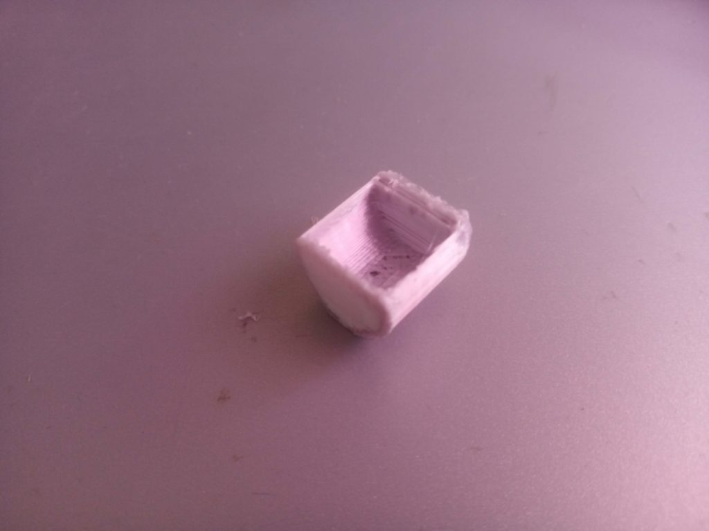
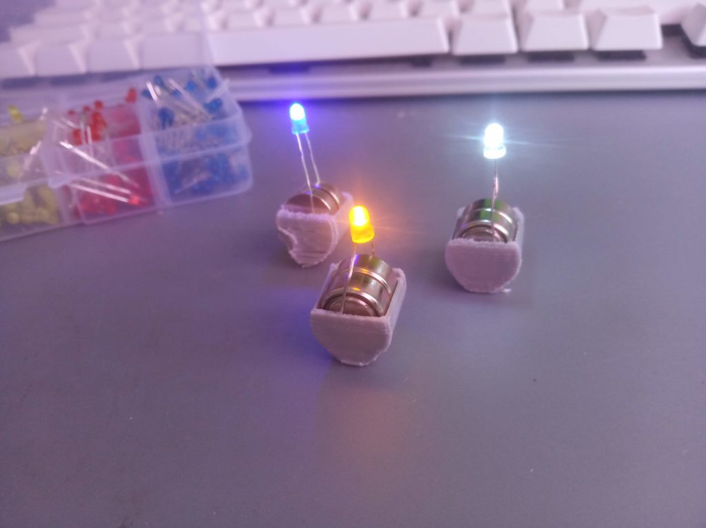
I 3D printed some AG13 battery holders, enough for two batteries. I slid the LED legs between the batteries and the plastic case. Result, we saw the light.

Some of the cases with AG13 batteries and LED’s in them.

This was printed on a Tronxy X1 printer with PLA+.

One of the cases, naked.

Here is the design on tinkercad.

This design would benefit from a flatter bottom so that they don’t topple over, and higher sides so that they hold the batteries better.

Categories
3D printing Retro gaming

ODROID XU4 cooling

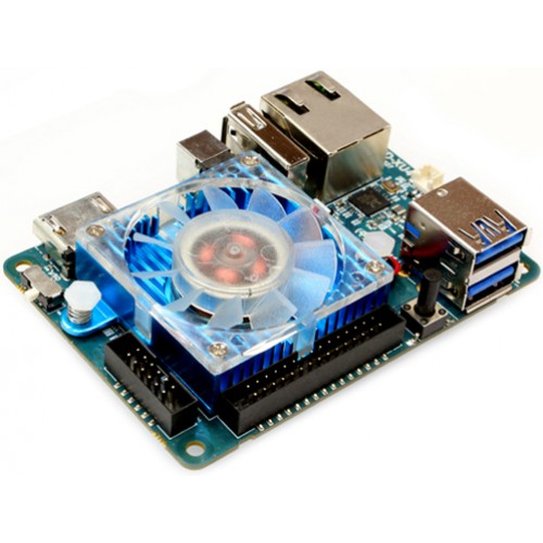
Building an arcade table using an ODROID XU4 SBC (Single Board Computer) to run the emulation under Linux, I found the stock 40mm fan that came with the XU4 was just too annoyingly noisy.

The XU4 with the annoyingly noisy fan.

I needed a solution which was not too tall because I was building this into an Ikea LACK side table so the available space was 54mm high. All the passive heatsink solutions I could find were too tall – the stock passive heatsink in the XU4Q was not enough to stop overheating on its own. I could still hear the buzzy 40mm case fan when enclosed in the table, I decided that I needed a simple, quieter solution which involved moving air and the existing heatsink.

As I also needed a case for the XU4, so I designed and 3D printed a case which would take a top mounted 80mm case fan. I’m using the eMMC to boot so there is a support for that. There are enough side holes for airflow, and to access the various XU4 ports. The XU4 is a snug fit, so much so that there is even a slot cut for the eMMC / SD Card selector switch which protrudes from the edge of the board. I have not found that I needed to screw the XU4 into the case, but that should be fine into one (or more I guess) of the corner quadrant pads.

Get the STL file from here: https://www.tinkercad.com/things/jQjhsvrBTEi

The case isn’t pretty, but it is functional and was designed to be hidden inside an Ikea table so it really didn’t need to be a diamond.

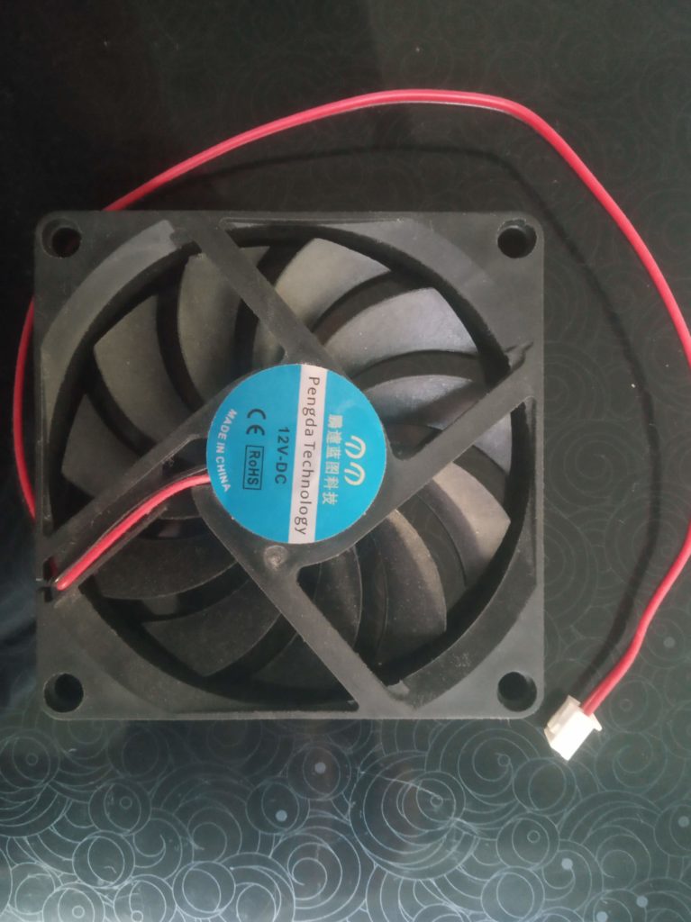
12V DC 10mm case fan

I sourced this 12V DC 2 pin case fan. Assuming the ebay link still exists, this one https://www.ebay.co.uk/itm/383664051536 which is 10mm high. I run this from the XU4, so at a maximum of 5V it runs slower than if run at 12V so quieter. Given that it moves more air than the stock 40mm fan, this seems to keep the board just as cool as the stock fan did, but significantly quieter.

This particular fan seems to be generic, there are lots on ebay / amazon which are similar. I was a bit worried it was going to be too noisy but it turned out to be pretty quiet, perhaps helped because it is being driven at 5V so spinning slower. Just a warning, some 12V fans may not work at 5V. Depending on your available space, you may be able to use a 15mm, 20mm or 25mm width fan. Having a larger area for the bearings, you may find that these fans can be made quieter, so you may be able to use a 5V 80mm case fan. If your fan has more than 2 wires, you should find that you only need to connect the positive and negative, the others can be left un-connected.

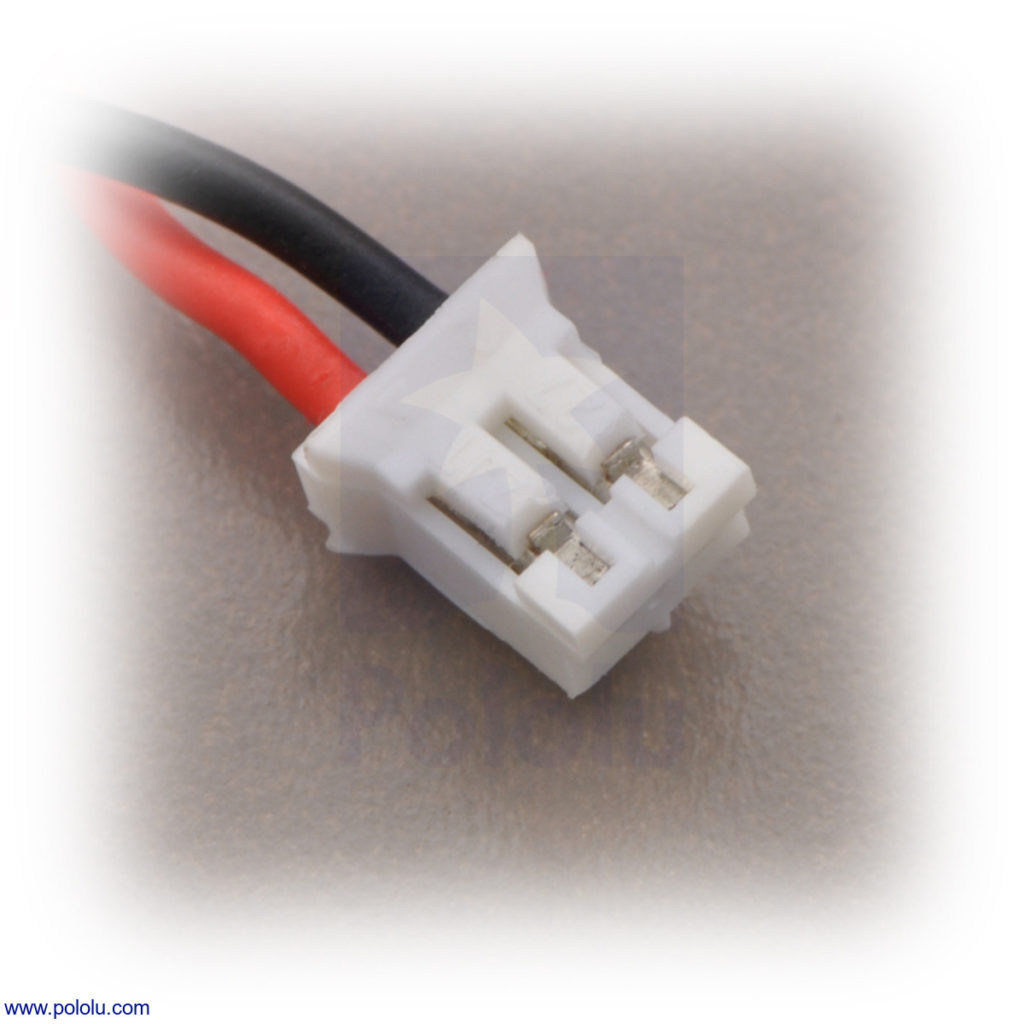
Female JST 1.25 pitch 2 pin connector

Like all case fans I’ve ever come across, this one comes with the wrong sized connector for an XU4 mother board, so I replaced the connector with this female 1.25mm pitch 2 pin JST connector. Again, assuming the link is still there, these ones: https://www.ebay.co.uk/itm/284270706948. This will require some soldering. Once connected, I screwed the fan to the lugs on the top of the case to keep it all secure.

I ran some prime95 tests and could not get the XU4 processor above 85 degrees C. In normal use, running the Naomi / Dreamcast emulator (lr-reicast) from Emulationstation / Retroarch, was probably about the most intensive and the core temperature hung around the 70-74 degrees C mark. This is also sharing a pretty small space with an Iiyama ProLite P1904S which has been dismantled but is still quite a warm beast.

If I did this again I think that I’d use the XU4Q model with the large passive heatsink, using this case / fan to contain and cool that, I think that it would fit ok but may need a shim or slight re-design to make the case walls higher.

I don’t have one but from what I’ve read, this should work on an XU3 without modification. For a Raspberry Pi you would need to do a little modification to the case design. On the Pi you would use dupont style female connectors with a 2.54mm pitch instead of the 1.25mm pitch 2 pin JST connector and connect the red wire to the +5V (GPIO 4) pin and the black one to Ground (GPIO 6) pin.

Ikea LACK arcade table

Here is the finished arcade table in case you are interested, we are very pleased with it all in all. I’ll write up how that was made when I get a chance.

Categories
Raspberry Pi

Super Capacitor testing

THIS IS FOR AN ODROID XU4 which has 1.8V max on GPIO logic, should also work in a Raspberry Pi but untested.

Working with Super Capacitors is super dangerous, they may burn you or weld your skin to something else, or give you a very nasty shock. Be very careful not to short the capacitor + and -, or feed them at a higher rating than is suitable. Please google super capacitors and understand how they work before playing with them.

  • 2 x 1.5 Ohm 5W resistor (R1, R2)
  • 2 x 5A Schottky diode (D1,D2)
  • 2 x 10F 2.7V capacitor (C1,C2)
  • 2 x 100R resistor (R3,R4)
  • 3 x 1K resistor (R5, R6, R7)
  • 1 x XL6009 Step up & down convertor module

5.2V input from 5A PSU, up and down convertor is set to output 5.1V output.

       +---R1---D1------+
in     |        >|      |
+5--+--+                +-----+---+-\
    |  |        >|      |    +|   |  -\         out
   R5  +---R2---D2------+    C1   |    -+----+- +5
   R6                        -|  R3     |step|
    +----<1.8V to GPIO        +---+     |up &|
    |                        +|   |     |down|
   R7                        C2  R4    -+---+-- -0
in  |                        -|   |  -/          out
-0--+-------------------------+---+-/

The voltage to a GPIO pin on the XU4 will be <1.8V (1.6V ish) whilst the input is 5.2V. A shell script should check the state of this pin and trigger a shutdown when the voltage drops below .5V.

Step Up Step down to provide 5.1V output no matter what the input is. Input min for this XL6009 module is 3.8V and it can be fed at 3A max.

Work in progress, this circuit is currently not working correctly.

Categories
Graphics

Create montage from lots of images on the CLI

I wanted to create a montage from a bunch of images in the same directory. I want to end up with something like the image below. I wanted it to look like a bunch of Polaroids haphazardly arranged on a pinboard.

Montage
Example montage

I use bash under Linux. To start with, update and install imagemagick.

sudo apt update
sudo apt install imagemagick

Now create a little script in the same directory as the images I want to use. You can change this script your hearts content.

cat >montage.sh <<EOS
#!/bin/bash
numberofimages=24
center=0
thumbsize=480
offset=400
yoffset=0
count=0
tmpfile=/tmp/montage-tmp.png
outfile=montage-final.png
background=transparent
files=`ls -altr `find . -name 'IMG_*.jpg' -type f -print` | grep -v $outfile | tail -$numberofimages | awk '{ print $9 }'`;
for image in $files
do
# Get image size and determine its virtual canvas
# read, thumbnail, image to a temp file.
convert -size 500x500 "$image" -thumbnail ${thumbsize}x${thumbsize} -bordercolor snow -background black -density 96x96 +polaroid $tmpfile
# Sort out the Y offset to get 6 across and 4 down
if (($count % 6 == 0 )); then yoffset=$(($yoffset+$thumbsize));
center=0;
fi
count=$((count+1));
# location so as to place it's center at the current position.
xpos=`convert "$tmpfile" -format "%[fx: $center - w/2 ]" info:`
ypos=`convert "$tmpfile" -format "%[fx: - h/2 ]" info:`
ypos=$(awk "BEGIN { print $ypos+$yoffset; exit }")
# $xpos and $ypos may be positive, so they may need a '+' sign
xpos=`echo "+$xpos" | sed 's/+-/-/'`
ypos=`echo "+$ypos" | sed 's/+-/-/'`
# Output the image into the pipeline for placement on canvas
# at the position (for top-left corner) calculated
convert -page $xpos$ypos "$tmpfile" MIFF:-
# Increment position for next image
center=`convert xc: -format "%[fx: $center + $offset ]" info:`
done |
# Read the pipeline of the images output from the above loop
# and create the canvas. Repage the virtual canvas, add some
# extra border space and output it.
convert -background "$background" MIFF:- -layers merge +repage -bordercolor "$background" -border 5x5 $outfile
EOS

Now to the script executable and run it.

chmod +x montage.sh
./montage.sh

Without any changes, when you run montage.sh it will grab all the files named IMG_*.jpg in the current directory and generate a montage.

Tweak the various variables at the top of the code to get the image right for you. If your files are named something different, change the ‘IMG_*.jpg’ string to match the names of your files in the files= statement.

Categories
Linux

Magicforce Smart 68 key mechanical keyboard – Linux mappings

Given I’m working from home I thought I’d set up a more permanent workspace instead of using a laptop. Doing away with the laptop keyboard I realised that we didn’t have a free standalone keyboard in the house so I went shopping on eBay. After a bit of background reading I decided I fancied trying a ‘mechanical’ keyboard. A distant memory is enjoying using the original IBM PC keyboards (I used the Model F) with their long travel and clicky keys.

I didn’t want a full size keyboard, I have no use for the number pad, its where I want my mouse to be. I really wanted white to match the decor, and I specifically wanted the cursor keys a little separate from the shift / enter keys. There were a few on eBay under my £30 budget but mainly black, or in China and in this case I couldn’t wait that long. So I’ve ended up with a “Magicforce | smart 68 Keys Mini Mechanical Keyboard” as it says on the back, a blue switch model, at £29 delivered. This was 2nd hand but I could see from the pictures that this keyboard was in pretty good condition anyway and these are really easy to clean because all the key caps are designed to come off, to be swapped even.
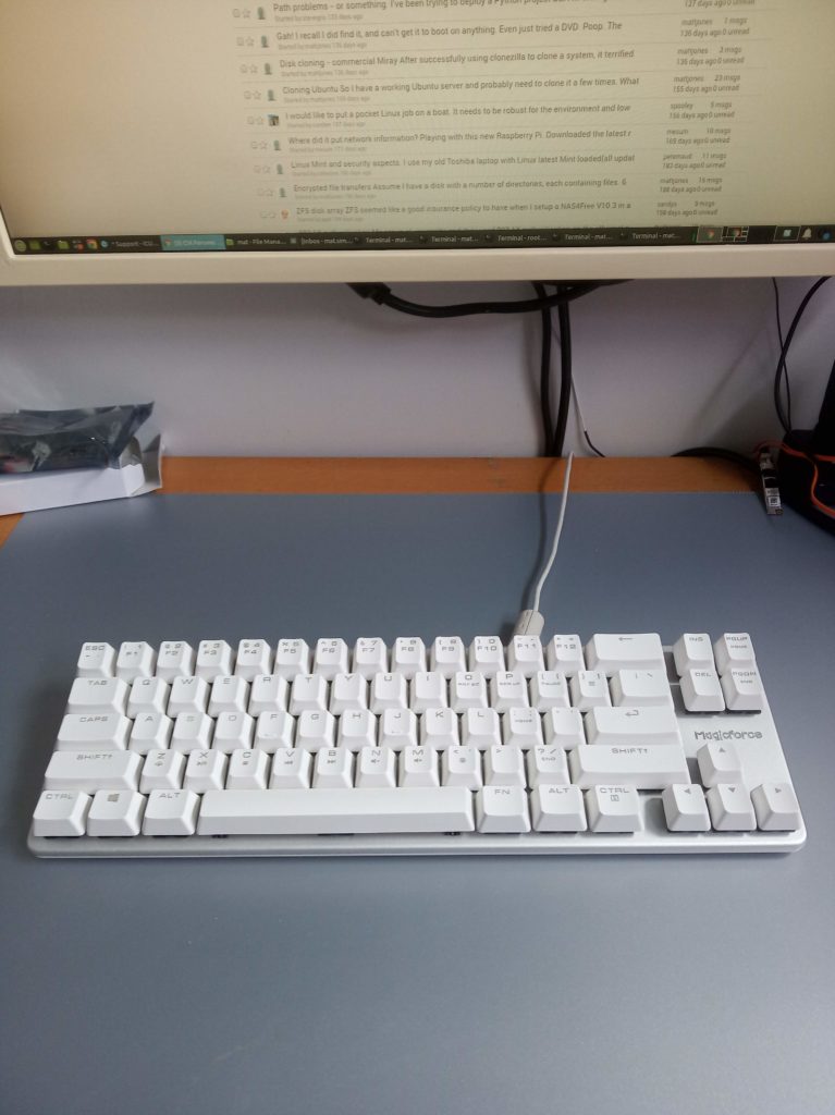
Magicforce Smart 68 key Mechanical Keyboard
After a few days of using it, its a great keyboard, though for the UK it could really do with an extra key. Now I’ve mapped the keys to my liking I can live with this though. I saw that there were some 69 key versions of this keyboard so perhaps this has been addressed already.

Anyway, if you have a keyboard and its not quite working for you, this is how I remapped mine:

I selected a Generic 104 key PC keyboard, with English (UK) layout, though I understand that perhaps selecting a US keyboard maps most keys properly, the UK layout does at least change the Shift-3 to a pound sign.

To backup the existing keyboard mappings:
xmodmap -pke >~/.Xmodmap-original

Use xev to see what key is mapped when a particular key is pressed:
xev -event keyboard -name HoverOverMe -geometry 300x20

If you cannot get the relevant key from xev (like if its not been mapped yet) you can get a list of all the keys / keycodes currently set up, though some of these are wrong e.g. three is 3.:
sudo dumpkeys -l >/tmp/keycodes

Use xmodmap to replace change a keycode to something else.
xmodmap -e "<keycode> = <keysym> <keysym> <keysym> <keysym> <keysym> <keysym>"
The sequence of these mappings is: Key, Shift+Key, mode_switch+Key, mode_switch+Shift+Key, AltGr+Key, AltGr+Shift+Key.
AltGr means the right alt, on this keyboard at least. To skip a column use NoSymbol as the keysym.

On this Magicforce 68 key keyboard using Mint 19.3 xfce4 I’ve done the following:

xmodmap -e "keycode 11 = 2 quotedbl NoSymbol NoSymbol twosuperior"
xmodmap -e "keycode 12 = 3 sterling NoSymbol NoSymbol numbersign"
xmodmap -e "keycode 48 = apostrophe at NoSymbol NoSymbol grave"
xmodmap -e "keycode 49 = NoSymbol asciitilde"
xmodmap -e "keycode 51 = backslash bar NoSymbol NoSymbol numbersign"
xmodmap -e "keycode 66 = NoSymbol Caps_Lock"

Yes, I rarely use CAPS (what is the point of it – a conversation for another day) and I tend only press it by mistake, so this makes CAPS only work with SHIFT-CAPS. Shame to lose all that keyboard real-estate but mapping another key to it doesn’t make sense to me. Shame though because on this keyboard there is a cool green backlight under the key.

To save the layout use the command:
xmodmap -pke >~/.Xmodmap

Make these mappings go live at startup (there are lots of ways to do this, this seems the easiest, you could make it a systemd service or something though).

cat > ~/.config/autostart/keyboard-mappings-MF68.desktop <<EOC
[Desktop Entry]
Encoding=UTF-8
Version=0.9.4
Type=Application
Name=Keyboard mappings for Magicforce 68
Comment=Keyboard mappings for Magicforce 68 by Mat Sims
Exec=/usr/bin/xmodmap ~/.Xmodmap
OnlyShowIn=XFCE;
RunHook=0
StartupNotify=false
Terminal=false
Hidden=false
EOC

You can run xmodmap ~/.Xmodmap anytime to set them. I find that on Mint 19.3 xfce4, after running xmodmap, xfsettingsd starts using too much CPU for an extended period. Give it a minute or so and it does normally calm down but if not, kill it and it should restart and behave.

If you find that you have messed up the keyboard you can get back the original settings with:
xmodmap ~/.Xmodmap-original

Categories
Uncategorized

Fake USB memory sticks from ebay.

I bought a 256GB USB / OTG memory stick from ebay member activeit_force. Their advert title says “64GB,128GB,256GB OTG USB 2.0 Flash Drive Memory Thumb Key Stick Pen Storage NEW”. I chose 256GB from the offered drop down list. I noted that buried in their description it says “These memory sticks are a Quality product and have been professionally upgraded, as such the capacity of these memory sticks can vary from 8GB to 64GB, 128GB, 256 GB, 512GB & 1TB respectively. All of our memory sticks are guaranteed have a minimum capacity of 8GB.”. So not saying that you may not get the capacity you selected just that they are different sizes.

So I received a USB stick with *2TB* stamped on it. I popped it in a Windows machine and it reports that it is a 1.90TB removable drive. I ran H2testw on it and this reported that after 15.1GB data was getting corrupted. So, this was not the capacity I selected and paid for. I reported this to ebay who refunded the item. I suggested that they should stop this seller from selling these items because such a sale is fraudulent. Needless to say, ebay have not stopped this seller from selling these items. The seller did not ask for the item back.

Considering the true size of this device is 15.1GB, I’ve used MiniTool Partition Wizard to create a 15GB NTFS partition, formatted it and re-tested with H2testw. This now reports that it is valid drive, no corruption.

So, I’ve got a free 15GB usb stick which I can also plug into my phone. Perhaps if everyone got their money back then used them as lower capacity devices people would stop selling these fake devices.

Categories
Linux Raspberry Pi

Raspberry PI 2 / 3 with 5″ touchscreen LCD

I managed to get a cheap 5″ LCD HDMI touchscreen from Ebay for my 80’s game emulator. This is an 800×480 panel using an XPT2046 to provide the resistive touch screen, a similar one can be bought here: Raspberry Pi 2 HDMI LCD Screen

A lot of the information on the Internet made it look like getting this screen working with the RPi was going to be a bit of a chore, but I found that out of the box Raspbian Jessie seems to work well with only a few configuration changes.

This screen attaches to the RPi2/3 via a clever 180 degree HDMI connector, and also via the GPIO so it is quite a secure fit. Metal standoffs are also included to keep the LCD and Raspberry Pi safe from harm. You can plug the power either into the power socket on the panel, or the RPI. Powering both screen and RPi from a 2a charger, and a battery pack meant for phone recharging rated at 5200 mAh, 3.7v with 2.1a output worked well.

The RPi is probably set to output video at 640×480, so setting the following in /boot/config.txt forces the 800×480 output:
# Force 800×480 for 5″ lcd display
hdmi_group=2
hdmi_mode=1
hdmi_mode=87
hdmi_cvt=800 480 60 6 0 0 0

The touchscreen didn’t work out of the box either, but adding the following to /boot/config.txt did the trick:
dtparam=spi=on
dtoverlay=ads7846,penirq=25,speed=10000,penirq_pull=2,xohms=150

That got the touchscreen working, but it wasn’t calibrated and there is no right click. The following fixed this:
wget http://github.com/downloads/tias/xinput_calibrator/xinput_calibrator-0.7.5.tar.gz
tar -xvf xinput_calibrator-0.7.5.tar.gz
cd xinput_calibrator-0.7.5.tar.gz
sudo apt-get install libx11-dev libxext-dev libxi-dev x11proto-input-dev
./configure
make
sudo make install

Run the calibration from the Application | System menu, locate all 4 corners and it will output some data, copy the data (starting Section) into the file below. This also includes code to emulate right click with a long press:
su
cat >/usr/share/X11/xorg.conf.d/01-input.conf
Section “InputClass”
Identifier “calibration”
MatchProduct “ADS7846 Touchscreen”
Option “Calibration” “141 4009 196 3966”
Option “EmulateThirdButton” “1”
Option “EmulateThirdButtonTimeout” “750”
Option “EmulateThirdButtonMoveThreshold” “30”
EndSection

Categories
DIY Raspberry Pi Retro gaming

DIY Raspberry PI portable arcade box with included screen and arcade controls

Since about 1997 when I first found Mame I’ve wanted a decent arcade gaming platform to play games like Street Fighter, Asteroids, Outrun, Pacman, Space Invaders, Bubble Bobble and the like.. I’ve thought about upright cabinets, cocktail cabinets but with no space and 3 kids these are still a pipe dream. Over the years I’ve tried putting arcade emulators on various machines running Windows and Linux, with with USB controllers and dedicated arcade controllers, none of which is quite what I’m looking for.

For a while I considered using a tablet / phone but with the advent of the Single Board Computer (SBC) like the Raspberry Pi I’ve designed and built a standalone counter top arcade gaming system, with built-in arcade controls, display, processing unit, battery, speakers and power on / off, etc.

I used the following:

£10 Square wooden box external 340mm x 250mm x 50mm
£20 Arcade Controls (joystick, buttons, Zero Delay USB encoder)
£ 3 USB travel speaker
£31 Raspberry Pi 3
£11 Power bar
£ 9 5″ 800×480 XPT2046 HDMI LCD
£ 4 A4 Perspex sheet I chose purple, the choice is yours
£ 2 Power switch
£ 4 Pack of 3 Male USB A to Micro B
£ 6 Spray on Lacquer
Some thin electrical wire
Undercoat / primer
Left over sparkly paint

Tools-wise I used:
Electric drill, Li-Ion battery is the best
Hole saw kit for 22mm, 24mm and 30mm holes
Jigsaw
Jigsaw blades specially for cutting Acrylic
Rasps

I started with the unpainted wooden box.

Arcade box before modifications

I gave it a sand and a clean, and then marked out the holes for the screen and arcade controls. I used some paper on which I’d drawn some grid lines, and then marked out where I wanted the screen, the joystick and the buttons to go. 22mm for the joystick, 24mm for the 2 smaller side buttons and 30mm for the larger top mounted buttons. I then laid that onto the box and pushed through with a pencil to mark out the hole centres, and the corners of the screen.

Arcade box with joystick Arcade controls

To cut the wooden box for the LCD panel I drilled some small pilot holes in the corners I’d marked out. I made this the size of the front of the LCD panel so that it fit snugly, the perspex goes on top and overlaps the LCD slightly making everything look neat. I used a small drill bit, wider than the jigsaw blade width. I started drilling inside the line so that the edge of the drill bit was on the line. I drilled about 5 or 6 holes next to each other along the line until it was long enough to fit the jigsaw blade. Once I’d done each corner I use the jigsaw. I finished with the wide rasp with square corners.

Cutting the holes for the joystick and top mounted buttons I placed a block under the top because it is a little flexible without the perspex.

Once I had cut all the holes I needed in the box, I put on a couple of coats of undercoat / primer, inside and out, sanding the outside between each coat with a very fine sandpaper. Then after cleaning I used a roller to give it 3 coats of paint on the outside only, sanding between each coat with a very fine sandpaper. Once the last coat was on I left it to dry for 24 hours. Then used a clear lacquer spray to finish the box, the trick here is lots of very light coats, otherwise the lacquer pools and runs. I did around 4 coats on the bottom / sides first leaving 5 minutes between each coat. I think I ended up doing 8 coats on the top / sides, I didn’t intentionally spray lacquer where the perspex was going to cover. I left this to dry for 24 hours.

To cut the perspex for the LCD panel I used the same technique as for the wooden box except the following. I put the perspex on a wooden block so that any exit marks on the bottom of the perspex were minimised. I set the jigsaw set to its fastest setting. I clamped a metal rule to the perspex with some cloth to ensure it didn’t scratch the surface to help keep the line straight. The hole in the perspex should be smaller than the hole in the wooden box, to overlap the edges of the LCD you don’t want to see.

IMG_20160808_070554

To cut the perspex for the buttons and joystick is similar. Using the correct sized hole saw – I used 22mm for the joystick and 30mm for the larger buttons. I’d already marked on the perspex where the buttons were located. I put the perspex onto a wooden block and drilled into that to ensure the underside of the perspex was not damaged.

IMG_20160808_070258
In the above picture I’m running Mame, though now its running RetroPie so its also emulating NES, SNES, Mame, PS2, N64 as well as running Duke Nukem 3D, Doom, Quake, and of course, an Atari VCS…

Categories
Linux

Dell 1350cnw on Linux

Getting a Dell 1350cnw working on Ubuntu 64bit 13.10 and higher is much more work than it should be.

This colour Laser (LED really) printer looks lovely on paper, small footprint, USB/Wifi/LAN connectivity, reasonable supply costs and great quality. They are also very cheap right now, I got one hardly used from ebay with half full toner and a complete spare toner set for £30! Ok, getting connected to WiFi is a bit of a pain because of the awful text entry system through the printers panel, ensure that once it is connected you allocate it an fixed IP address using Mac address allocation or whatever your DHCP implementation (often in your broadband router if this is at your home) calls it.

Once connected to the Wifi, it works great with Windows machines and probably 32bit Linux (is anyone still using this) but with 64bit Linux it is a bit of a pain, here is what I did to overcome this using the Xerox Phaser 6000B drivers and CUPS – thanks Apple!

I have carried this procedure out on both Ubuntu Mate 15.04 64bit, Ubuntu Studio 15.04-18.04 64bit, Mint 18.3 and 19.3 distributions.

Get the deb file from http://www.support.xerox.com/support/phaser-6010/downloads/enus.html?operatingSystem=linux

unzip xerox-phaser-6000-6010_1.0-1_i386
sudo dpkg --add-architecture i386
sudo apt-get update
sudo apt-get install libc6:i386 libncurses5:i386 
sudo apt-get install libstdc++6:i386 libcupsimage2:i386
sudo dpkg -i xerox-phaser-6000-6010_1.0-1_i386.deb
apt-get -f install
cp /usr/share/ppd/Xerox/Xerox_Phaser_6000B.ppd.gz /tmp
gunzip /tmp/Xerox_Phaser_6000B.ppd.gz

Add your unix username to the lp group:

sudo gpasswd -a  lp
sudo gpasswd -a root lp

DefaultAuthType Negotiate
edit your /etc/cups/cupsd.conf changing DefaultAuthType from Negotiate to Basic.

Point your web browser at Dell 1350cnw on Linux CUPS administration pages: http://localhost:631
You will need to login with your unix username and password.

Under Administration I ticked:

Share printers connected to this system Max client 100
Allow printing from the Internet
Allow remote administration
Allow users to cancel any job
Preserve job history
Maximum jobs 500
Remain metadata Yes
Retain Documents 1d
Save debugging information Max log size: 0

Make sure your printer is on.

Add the printer. 2 Dell 1350cnw’s appeared under Network Printers, I picked: “Dell 1350cnw Color Printer; NIC 17.10,ESS 201008241506 (Dell 1350cnw Color Printer)” and clicked Continue.
I ticked Sharing to Share this printer and Continue.
I ignored the Make / Model, etc and clicked Choose file and pointed to the /tmp/Xerox_Phaser_6000B.ppd file we stored above and clicked Add Printer.

On the next page I clicked Set Default options and that was it.

I was then able to successfully print a test page from CUPS and documents from Libre Office and from Chrome browser.